The Simudyne SDK allows you to define topologies, that is pairs of groups of agents equipped with a strategy of connection that defines links between them.
The following section will guide you through:
- What Links are and how they permit interactions between agents.
- How to create topologies using tools called
GroupsandConnectors. - An overview of the
Connectorsavailable and some of their advanced features. - How to synthesize a graph topology on a
Groupusing probabilistic distributions defining the graph properties.
Agent Links
Agent-Based Modelling aims to provide a bottom up approach to simulating different situations. With entities, called agents, that have their own behaviour and interact with one and other.
In the Simudyne SDK, those interactions are made possible through message passing. As we shall see, Links are a good way to ease this process.
Registering Agents And Links
It is necessary to register Agents and Links in the init of your model. This is required in order to assure that the shape of your data remains constant during the course of the simulation.
To register links and agents simply call the provided methods passing in all of the Agents and Links you require.
AgentBasedModels (Java)
@Override
public void init() {
  registerAgentTypes(MyAgent.class);
  registerLinkTypes(MyLink.class);
}
Agent Links as a Communication Mechanism
Each Agent can register links from itself to others agents. Its links allow it to have a reference to other agents it knows or it communicates with so that it can send messages to them.
From one agent, you can create links to other agents using their IDs like so:
Adding a link (Java)
MyAgent agent;
// The ID of another agent to connect to
long targetID;

agent.addLink(targetID, Links.Neighbour.class);
Where we define a Neighbour link class that extends Empty.Link. Defining meaningful link names is encouraged in order to avoid confusion as your models get more complex.
Defining a link (Java)
public class Links {
  public static class Neighbour extends Link.Empty {}
}
Links are not just simple references: they can embed data as well. This data generally deals with a relation between an agent and one of its peers.
Here is how to create a Link that embeds data. First, define a specific class for your link:
Definition of a Link class (Java)
public class MyLink extends Link {
  int someData;
}
When adding links you can now provide a serializable consumer to addLink in order to assign link fields.
Adding a custom Link with fields(Java)
agent.addLink(targetID, MyLink.class, myLink -> myLink.someData=2));
The Link can in the same manner:
- be accessed by an agent using
getLinks()andgetLinksTo() - be removed by an agent using
removeLinks()andremoveLinksTo()
An agent can also check if it has links with, hasLinks() and hasLinksTo().
When an agent wants to interact with its environment or with its peers, it has to send messages to them. An agent can:
- Send messages to a particular agent; the sender has to use the id of the agent it wants to send a message to.
- Send message along its links; this way all the agents that are connected to the sender will get the messages.
Links give rise to specific behaviours of the model.
The Simudyne SDK exposes tools to automate and ease the creation of links and complex link structures known as topologies.
The next part will get you started with topologies.
Getting started with Topologies
Before getting started, let's define concepts introduced in the Simudyne SDK to create topologies, that is the concepts of Group and Connectors.
Groups as sets of agents
Intuitively, in modelling one tends to define their models in terms of sets or groups of agents having identical properties and behaviours.
This is exactly what a Group in the Simudyne SDK is : a set of agents of a particular class. In a Group, all the agents are identical in the sense that they are instances of the same class. Thus a Group is parametrised by its type of agent and also by its size, the number of agents present in the Group.
Using a MyAgent class defined as above, Groups can be created using the AgentSystem like so:
Generating Groups (Java)
int nbAgents = 10;

// Creating a group of 10 agents of class MyAgent
Group<MyAgentClass> group = generateGroup(MyAgent.class, nbAgents);
After these snippets being executed and the system being set up, 10 agents will be spawned in the model and will live their life according to their behaviour defined in the model.
Note Group created is typed by the agent class (in this example MyAgentClass).
Connectors as macroscopic description of connections
Now that we have Groups, we would like to describe the way to connect their agents together.
Connectors implement this concept and are used to specify how to connect agents in one group together or how to connect agents of two different groups together.
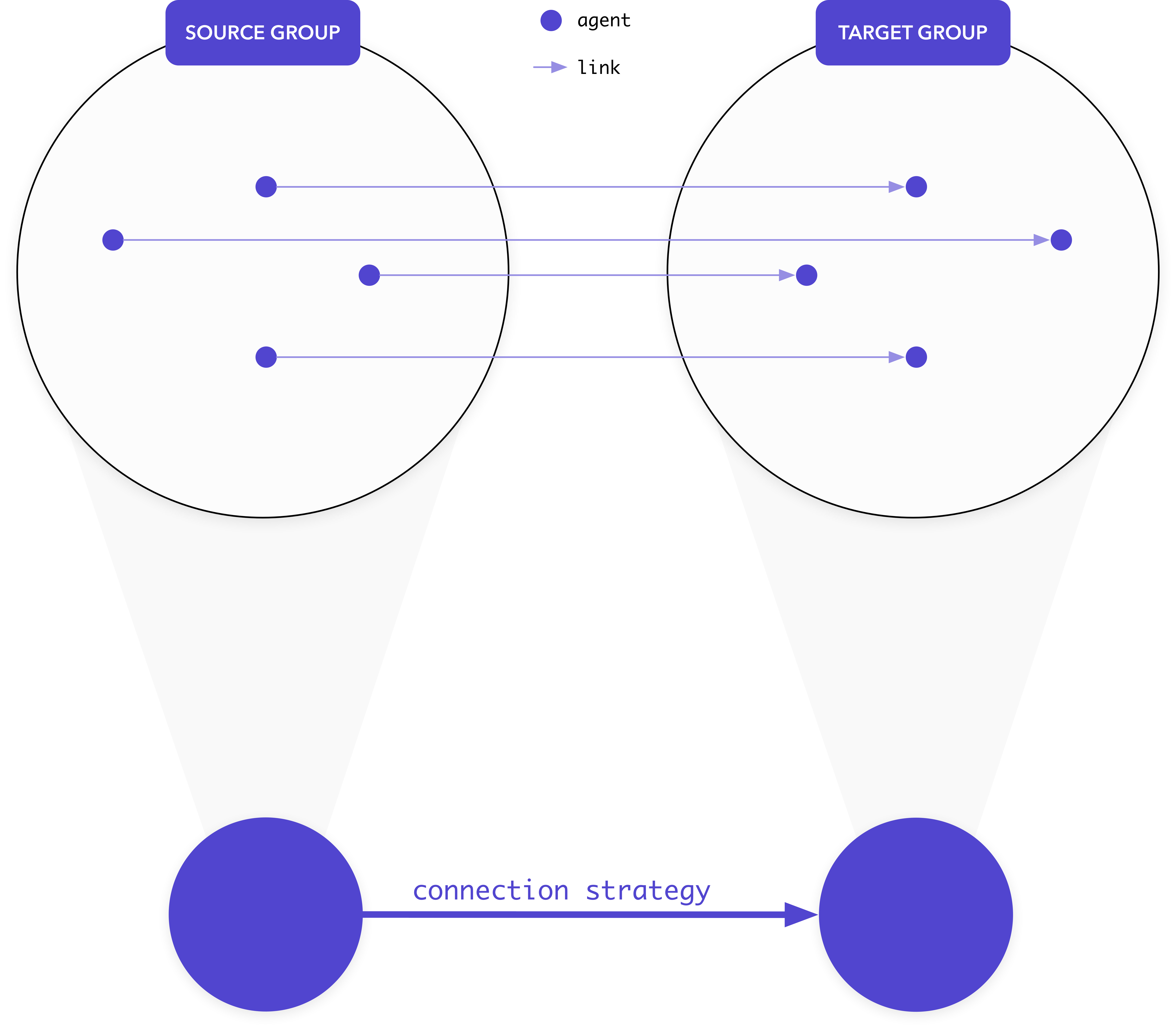
We provide different Connectors ready to use; here we are going to use the most popular and simple one, FullyConnected, to explains how to connect Groups together`.
Using this Connector, every agent from the source group will be connected to all other agents in the target group.
Let's create and connect to groups together:
FullyConnected on 2 Groups (Java)
Group<MyAgentClass> sourceGroup = generateGroup(MyAgent.class, 5);
Group<MyAgentClass> targetGroup = generateGroup(MyAgent.class, 5);

// Connecting the two groups together using the FullyConnected ConnectionStrategy
sourceGroup.fullyConnected(targetGroup, MyLink.class);
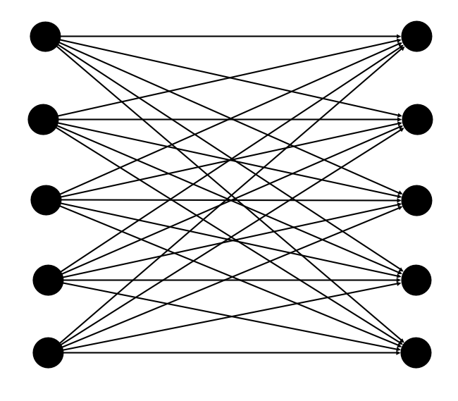
Similar to before, we create two Group using the system generateGroup() method. We then use fullyConnected() on the source group with the target group this Connector to register the topology. Here is a graphical representation - the nodes represent the agents and the edges their links:
You can also use a Connector on only one group. This group would be the source but also its own target. Taking a groups created above, we can link its agents using this Connector with this line:
Registering a ConnectionStrategy on a Group (Java)
Group<MyAgentClass> group = generateGroup(MyAgent.class, 5);

// FullyConnecting one group
group.fullyConnected(group, MyLink.class);
And that's all ! After the setup being setup, the agents would be created with their link as specified by the Connector.
Topologies as the alliance of Groups and Connectors
With those concept defined, you are now able to create topologies, that is a pair of Groups and Connectors!
More precisely, you are able:
- to create as many
Groupsof agents of a specific type and of a certain population as you want; - to create as many specific connections between as many
Groupsas you want, shall those groups be identical or different; - to parametrize the links created – i.e. embedding data in them.
- to define your own
Connectorsif you want to (see the following dedicated section)
Let's give an concrete example to recap but also show all the possibilities of this API.
Example: Transportation problem
Someone might want to simulate some transport problems using Agent Based Modelling. What they can begin with is defining the structure of countries and cities in a continent. One can come with this natural modelling using UML:
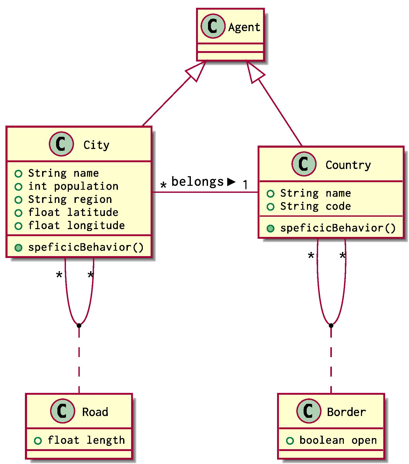
City and Country are two classes of agents that extend the class Agent used in Simudyne SDK. Each City belongs to one and only Country. Cities can be connected together via Roads and Countries can be adjacent on behalf of their Borders
Using our previous definition, the situation can be implemented using 2 groups of agents, a Group<City> and a Group<Country>.
You can firstly define your agents classes like so:
City and Country Definitions (Java)
public class City extends Agent<GlobalState> {
  String name;
  int population;
  String region;
  Float latitude;
  Float longitude;

  void specificBehavior() {
    // ...
  }
  // ...
}
You can also defined the Link classes:
public static class Links {
  public class Road extends Link {
    Float length;
  }

	public class Border extends Link {
    boolean open;
  }

  public class Country extends Link.Empty { }
}
Then in your model, you can generate groups of agents like so:
Groups Generation (Java)
class MyModel extends AgentBasedModel<GlobalState> {
  // ...

  @Override
  void setup(){
    Group<City> cities = generateGroup(City.class,10000);
    Group<Country> countries = generateGroup(Country.class,10);

    // ...
  }

  // ...
}
Here 10 00 Cities will be spawned, as well as 10 Countries.
For now they are not connected. You can proceed to 3 types of connections:
- connections between
Cities, withRoadsas links (as random connection) - connections between
Countries, withBordersas links (with all the Countries linked to each other) - connections between
Citiesand theirCountrywith no specific link (with Cities being uniformly distributed across Countries)
Group Connection (Java)
@Override
void setup(){
  Group<City> cities = generateGroup(City.class,10000);
  Group<Country> countries = generateGroup(Country.class,10);

  // Connectiong Cities together with Roads
  cities.smallWorldConnected(10,0.7, Road.class);

  // Connecting Countries together with Borders
  countries.fullyConnected(countries, Border.class);

  // Connecting Cities to their Country with a Country Link
  cities.partitionConnected(countries, Country.class);
}
To model random connections between Cities here, we use a SmallWorld.
And we are done !
Defining agents more precisely in Groups
For now, we only populated groups of agents without specifying their attributes. This can be changed using a optional parameter when using the system generateGroup() method.
This extra parameter is a function you have to define to inject data into each agent: using a dataInjector, you can have access to different information (such as the ID that will be given to the agent in the system but also a sequence ID that specify the place of the agent in its group) and tools like a pseudo-random number generator, SeededRandom.
Let's give an example with the class City defined above:
Specifying agents in Groups (Java)
Group<City> cities =
  generateGroup(City.class,10000, city -> {
    SeededRandom ran = city.getPrng();
    RealDistribution populationDistrib = ran.gaussian(43000,6000);
    RealDistribution coordinatesDistrib = ran.uniform(-10,20);

    // Changing the city fields
    city.population = (int) populationDistrib.sample();
    city.latitude = coordinatesDistrib.sample();
    city.longitude = coordinatesDistrib.sample();
  });
Here, we get access to the agent's pseudo random number generator that we have named ran. With this object, we the define two distributions to use to change fields for each city.
More precisely we choose to spawn Cities with:
- Their population being drawn from a normal distribution of mean `43000` and standard deviation `6000`.
- Their latitude and longitude being drawn from a uniform distribution on the interval `[-10, 20]`.
Defining links more precisely when using Connectors As it is the case for agent, link will be spawned with fields having default values. You can define the links to create for precisely using the optional lambda when connecting groups.
Here is an example with FullyConnected:
Defining Link (Java)
cities.fullyConnected(City.class, Road.class, road -> {
  SeededRandom ran = road.getPrng();
  RealDistribution lengthDistribution = ran.gaussian(50,25);

  road.length = lengthDistribution.sample();
});
Connectors
A summary of the Connectors available in the SDK as well as their parametrisation.
FullyConnected
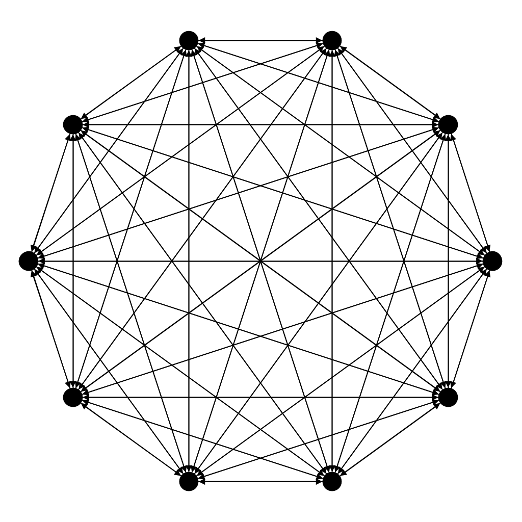
In a FullyConnected network, all source agents are connected to all target agents.
1 Group (Java)
group.fullyConnected(group, MyLink.class);
sourceGroup.fullyConnected(targetGroup, MyLink.class);
This connector can be used on one or two groups. In the latter case, the connection will be similar to connections in a complete bipartite graph (like connections between two layers in a simple artificial neural network).
2 Groups (Java)
sourceGroup.fullyConnected(targetGroup, MyLink.class);
This topology is also called Complete Graph in mathematics and graph theory.
PartitionConnected
In a PartitionConnected network, agents from the source group are equally connected to agents of the target group.
The behaviour of this connector adapts to the number of source and target agents:
- If the source is bigger than the target, target agents will be connected to several source agents
- If the two groups contain the same number of agents, then agents will be connected on a one to one basis.
- If the target is bigger than the source, source agents will be connected to several target agents.
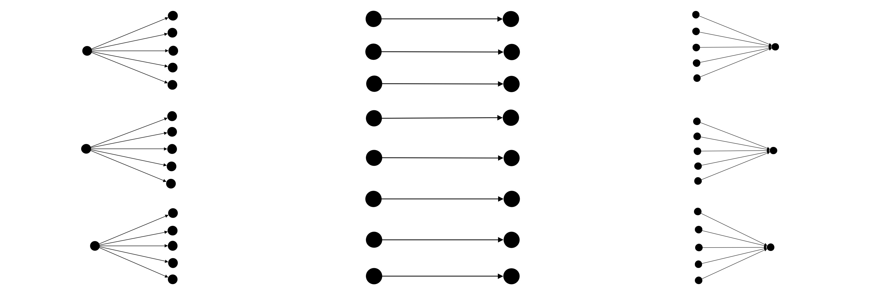
PartitionConnected - 2 Groups (Java)
sourceGroup.partitionConnected(targetGroup, MyLink.class);
PartitionConnected has two sub-strategies for connections.
Shard connections
The shard() sub-strategy will partition the two groups of agents in term of proximity of agents.
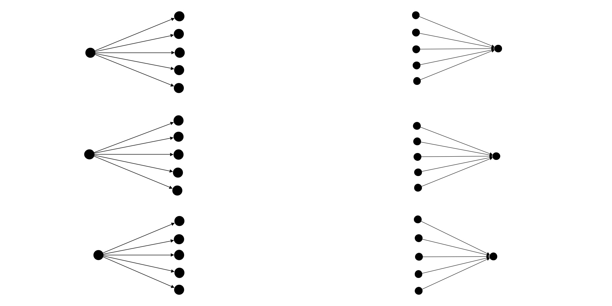
PartitionConnected -- Shard (Java)
sourceGroup.partitionConnected(targetGroup, MyLink.class).shard();
Weaved connections
The weave() sub-stategy will partition the two groups of agents weaving the links together.
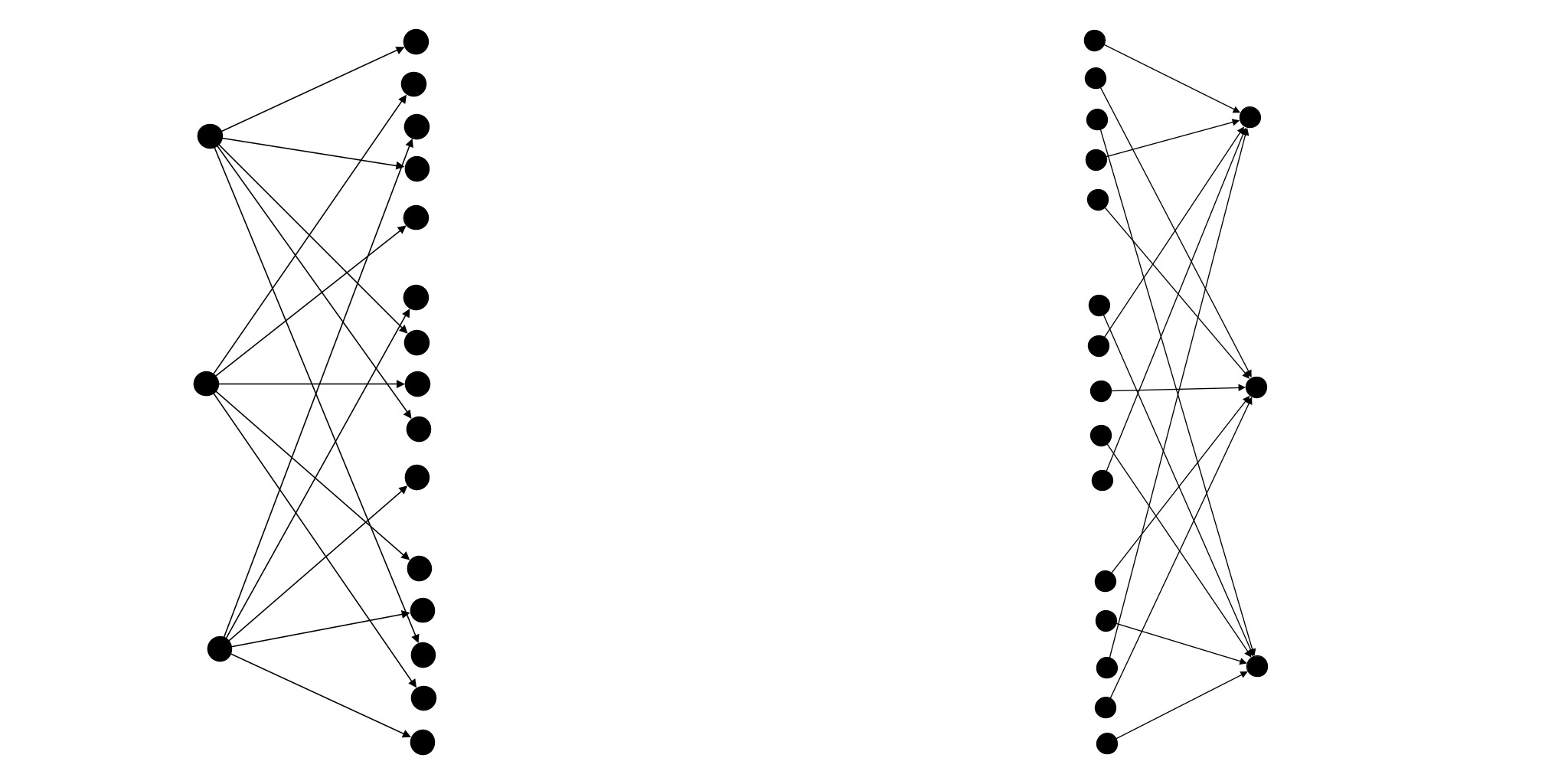
PartitionConnected -- Weave (Java)
sourceGroup.partitionConnected(targetGroup, MyLink.class).weave();
Used alone, those sub-strategies seems identical and will indeed give the same results. However if you use another connector on one of the groups this will give a completely different behaviour.
SmallWorldConnected
SmallWorldConnected operates on one group and will create a small-world network.
In essence, a small-world network is an intermediate between a ring lattice and a random graph.
It is parametrised by two coefficients:
inDegree, a positive integer that specifies the number of outgoing links to create for each agent - it must be strictly smaller thann, the number of agents in theGroup;beta, a double in[0,1]that specifies the degree of randomness of the graph
More exactly, inDegree is equal to the number of agents in the group minus one.
Furthermore, if beta is equal to 0, the graph will be a complete ring lattice and if beta is equal to 1 the graph will be completely random.
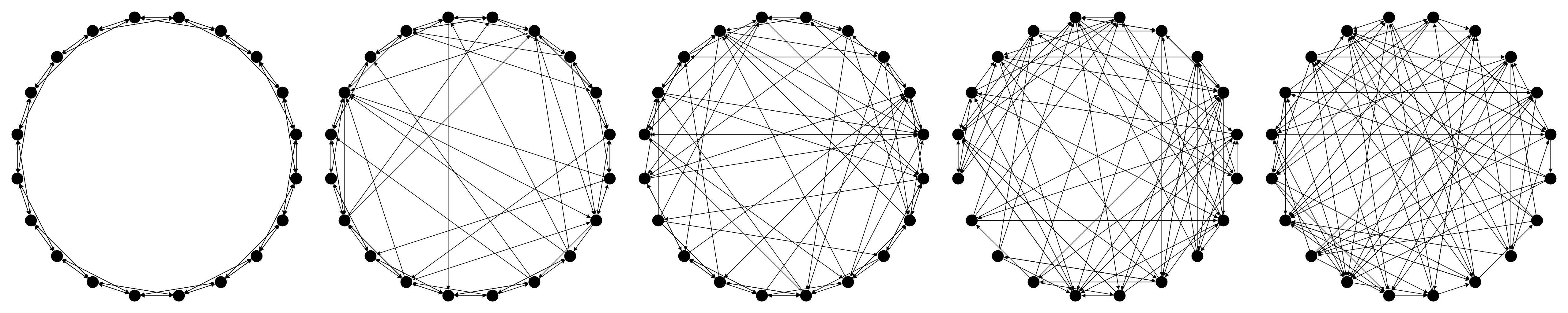
SmallWorldConnected (Java)
// the number of outgoing links to create for each agent
int inDegree;

// a double in `[0,1]` that specifies the degree of randomness of the graph
double beta;

group.smallWorldConnected(inDegree, beta, MyLink.class);
This type of structure has been used a lot to model social networks in simulations.
More about Small-World network on Wikipedia:
Small-world network - Wikipedia
GridConnected
GridConnected connects agents as if they were on a square grid. This is the main connector used for cellular automata.
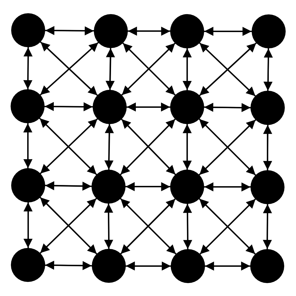
By default, the grid used is a square and is also responsive to the number of agents (its width is adapted so that all the agents can fit in it).
However you can change the grid using several sub-strategies, let's present them.
Wrapping the grid
The grid can be wrapped (so that it becomes a torus): this way, agents on a grid edge will be connected to the agent on the opposite edge.
This can be triggered using GridConnection.wrapped().
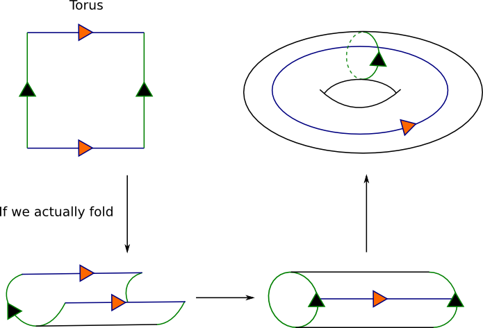
GridConnected -- wrapped2(Java)
group.gridConnected(MyLink.class).wrapped();
Specifying the width of the grid
By default, the grid is a square but you can make it a rectangle if you specify the width to use.
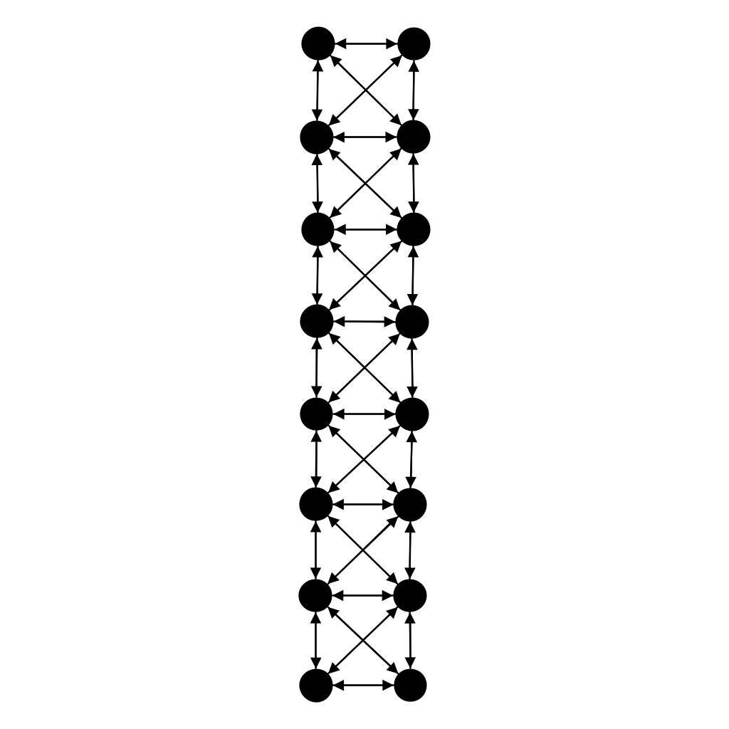
GridConnected -- width of 2(Java)
group.gridConnected(MyLink.class).width(2);
Changing the neighbourhood to use
By default and in normal cases, each agent is connected to 8 other agents, called neighbours.
This default neighbourhood is the Moore Neighbourhood defined for a Chebyshev distance of 1.
This is the common neighbourhood defined in a variety on agent based model like Conway's Game of Life or Thomas Schelling's models of segregation
This Chebyshev distance can be changed to a number n (supposed greater than 1), making each agents connected to (2 * n + 1)^2 - 1 other agents.
GridConnected -- Moore Neighbourhood (Java)
group.gridConnected(MyLink.class).mooreConnected();

// Specifying a distance for the neighboorhood.
int maxDistance;
group.gridConnected(MyLink.class).mooreConnected(maxDistance);
More about the Moore Neighbourhood on Wikipedia:
Moore Neighborhood - Wikipedia
The other neighbourhood available is the Von Neumann Neighbourhood that is by default defined for a Manhattan distance of 1. Using this neighbourhood, each agent is connected to 4 other agents.
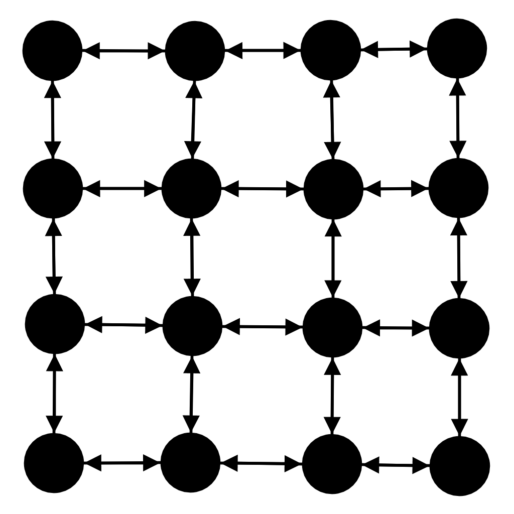
GridConnected -- Von Neumann Neighbourhood (Java)
group.gridConnected(MyLink.class).vonNeumannConnected();

// Specifying a distance for the neighboorhood.
int maxDistance;
group.gridConnected(MyLink.class).vonNeumannConnected(maxDistance);
This Manhattan distance can also be changed to a number n (supposed greater than 1), connecting agents to 2 * n * (n + 1) other agents.
More about the Von Neumann Neighbourhood on Wikipedia:
Von Neumann Neighbourhood - Wikipedia
BananaTree
A Banana Tree is a graph obtained by connecting one leaf of each of n copies of a star graph with a single root vertex that is distinct from all the stars.
Here are examples of different Banana Trees.
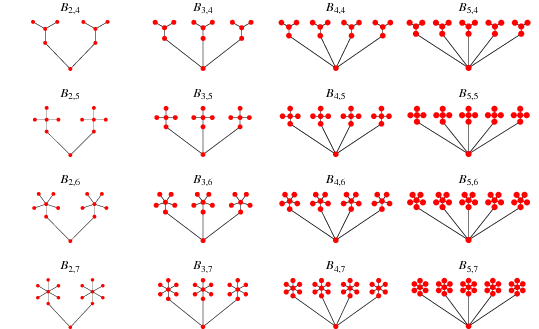
BananaTree(Java)
// the number of subgraphs to use
int nbStars;

group.bananaTreeConnected(nbStars, MyLink.class);
Banana Trees can be centred or not:
- In non-centred trees, each star is connected to the central node by one of its outer node.
- In centred trees, each star is connected to the central node by its own central node.
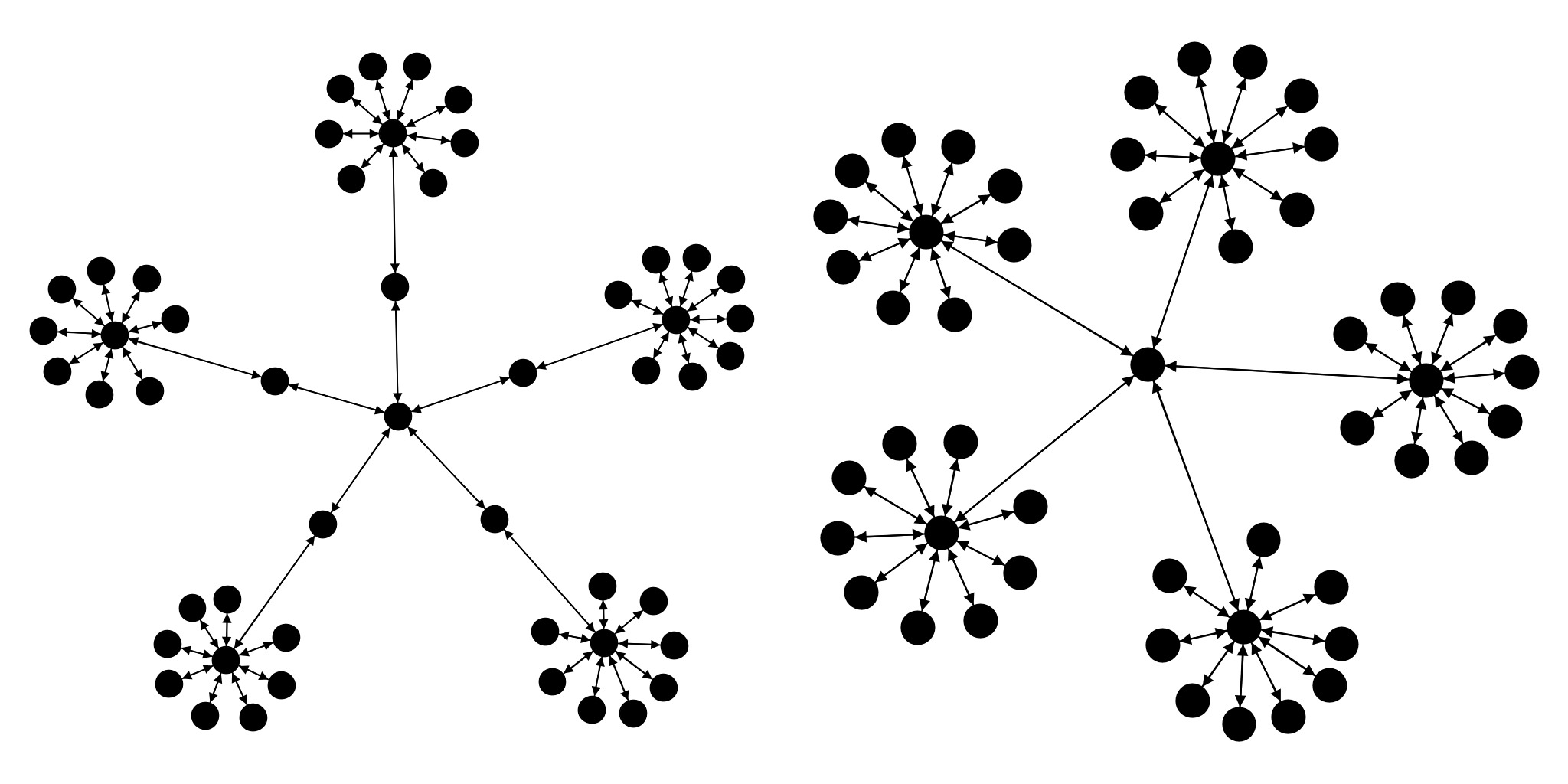
BananaTree -- Centered (Java)
group.bananaTreeConnected(nbStars, MyLink.class).setCentered();
GraphConnected
GraphConnected can be used to generate a graph using a degree distribution and a local clustering coefficient. The Apache commons math distributions are expected as the distribution parameters. Apache commons distributions can be created using the generator methods provided in the Simudyne class SeededRandom.
The degree distribution lower bound must be a positive number, and the clustering coefficient must have an upper bound of 1 and a lower bound of 0.
GraphConnected
SeededRandom randomGenerator = getContext().getPRNG();
PoissonDistribution degreeDistribution = randomGenerator.poison(10);
UniformRealDistribution clusterCoefficient = randomGenerator.uniform(0, 1);
group.graphConnected(degreeDistribution, clusterCoefficient, MyLink.class);
The way the degree distribution and clustering coefficent is used to create a graph internally is based on the Darwini method.
Composability of connectors
Connectors are composable: you can combine their parameters and different substrategies. Let's give an example using GridConnected:
Composing substrategies(Java)
// Using a flat square grid (default case)
group.gridConnected(MyLink.class);

// Using a wrapped grid
group.gridConnected(MyLink.class).wrapped();

// Using a flat grid of width w
group.gridConnected(MyLink.class).width(w);

// Using a grid with a different neighborhood definition
group.gridConnected(MyLink.class).vonNeumannConnected();

// Composition them all !
// Using a torus of width w with a Von Neumann neighborhood
group.gridConnected(MyLink.class).wrapped().width(w).vonNeumannConnected();
Connector Summary
With n and m being respectively the sourceGroup and targetGroup size, we can summaries the number of links created:
| Connector | # of links on 1 Group | # of links on 2 Groups |
|---|---|---|
| FullyConnected | n*(n-1) | n*m |
| PartitionConnected | n | max(n,m) |
| SmallWorldConnected | n*inDegree | Does not apply |
| GridConnected | 8 * w^2 - 12w + 4 with w = ceil(sqrt(n)) (in the base case ) | Does not apply |
| BananaTree | 2 * n - 2 | Does not apply |
Defining your own connector
The Simudyne SDK provides some useful connectors you can use to build ABM easily.
If the 'out the box' connections do not suffice, the Simudyne SDK lets you define and use your own connector. Here is how to proceed.
You first need to extend the the Connector abstract class like this:
Defining a Connector(Java)
public class CustomConnector<T> implements Connector {
    private final Class<T> linkClass;
    private final SerializableBiConsumer<InitContext, T> dataInjector;

    public CustomConnector(Class<T> linkClass,
                           SerializableBiConsumer<InitContext, T> dataInjector) {
        this.linkClass = linkClass;
        this.dataInjector = dataInjector;
    }

    @Override
    public void connectAgent(ConnectionInitializer connectInit,
                             GroupInformation sourceInfo,
                             GroupInformation targetInfo) {
        // ... the connection strategy is to define here
    }
}
The algorithm to use for you to define for CustomConnector is in connectAgent(). You will have to analytically define an algorithm that can be applied individually to each node.
In order to define this algorithm:
- the
GroupInformationsourceInfoandtargetInfogive you respectively global information about each of the group used as source and target for yourCustomConnector. - the
Agent, is the current agent and gives you access in your algorithm to a given node information.
Let's create a custom ConnectionStrategy that will connect each agent in a ring.
Example of definition of a Connector(Java)
public class CustomConnector<A extends Agent<?>, L extends Link> implements Connector {
  private final Class<L> linkClass;
  private final SerializableBiConsumer<A, L> dataInjector;

  public CustomConnector(Class<L> linkClass, SerializableBiConsumer<A, L> dataInjector) {
    this.linkClass = linkClass;
    this.dataInjector = dataInjector;
  }

  @Override
  public void connectAgent(Agent agent, GroupInformation sourceInfo, GroupInformation targetInfo) {
    agent.addLink(targetInfo.getBaseID(), linkClass, link -> dataInjector.accept(agent, link));
  }
}
You can then use your CustomConnector using Group.connect():
Using your CustomConnector (Java)
cellsGroup.connect(cellsGroup, new CustomConnector<>(MyLink.class, (cell, link) -> link.x = cell.id);